USE KUZZLE AS AN IOT BACKEND WITH ESP32 MCU #

Intro: Use Kuzzle as an IoT backend With ESP32 #
Kuzzle is an open-source backend. It can be installed on-premises, and it features a multi-protocol API allowing to integrate IoT devices.
This article explains how to develop an IoT application using an ESP32 module and Kuzzle, communicating using MQTT.
Specifically, we will build a basic IoT device featuring a RGB LED, and change its colors using Kuzzle's Admin Console.
Install Kuzzle #
The following guide allows you to quickly run a Kuzzle instance: Getting Started
By default, Kuzzle does not support MQTT communication, but it features an extensible protocol system: install our official MQTT Protocol to add MQTT capabilities.
To browse and manage your data, either install Kuzzle's administration console, or use the online version available here (although it is hosted online, no data will ever leave your network).
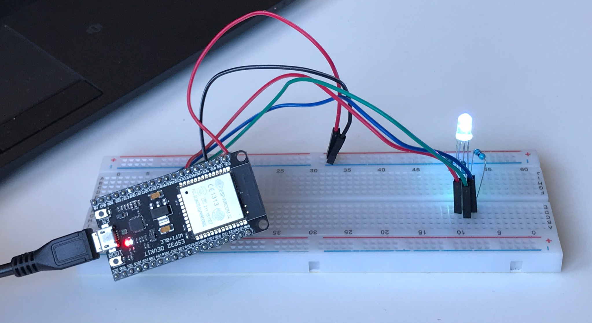
Components prerequisites #
For this tutorial, you need the following components:
- 1 × ESP32 DevKit C
- 1 × USB A / micro USB B cable
- 1 × PC running Linux
- 1 × RGB LED
- 3 × 100 ohm resistor
Preparing the Kuzzle IoT Environment #
Our IoT application requires a simple storage setup: a data index, data collections and their corresponding mappings.
Read our persistence layer documentation for more information.
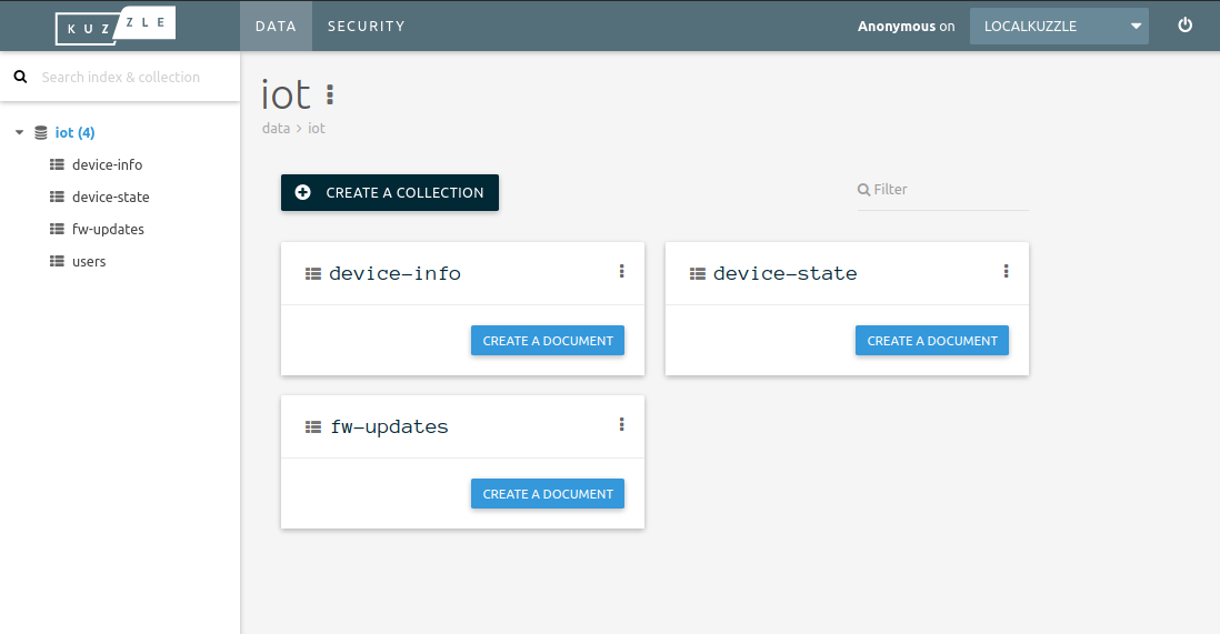
The script iot-deploy creates the necessary storage structures in a Kuzzle instance.
Once you have run the script, open the administration console. There should now be an iot index containing these 3 collections:
device-info: contains information about devices (proprietary, friendly name, ...)device-state: keeps track of the device state history. Also used to subscribe to state changesfw-update: keeps track of available firmware updates
This first tutorial only uses the device-state collection.
Preparing the ESP32 Development Environment #
First, install the ESP32 toolchain and SDK: https://esp-idf.readthedocs.io/en/latest/get-started/index.html
Then, create your project by cloning Espressif's application template:
$ git clone https://github.com/espressif/esp-idf-template my-connected-rgb-lightMake sure you are able to build and flash the application to your ESP32 module.

Dependencies #
To allow your application to communicate with Kuzzle, you need 2 components:
esp-mqtt: MQTT communication layer library for ESP32kuzzle-esp32: custom component, for communicating with Kuzzle over MQTT
Clone the esp-mqtt and kuzzle-esp32 components in the components folder to add them to your project:
$ git submodule add https://github.com/espressif/esp-mqtt components/esp-mqtt
$ git submodule add https://github.com/kuzzleio/kuzzle-esp32 components/kuzzle-esp32
(components must be located in the project's components subfolder, as explained in the Espressif build system documentation)
Your project folder structure should now look like this:
$ tree -d -L 2
.
├── components
│   ├── esp-mqtt
│   └── kuzzle-esp32
└── main
Wiring the RGB LED to ESP32 DevKit C #
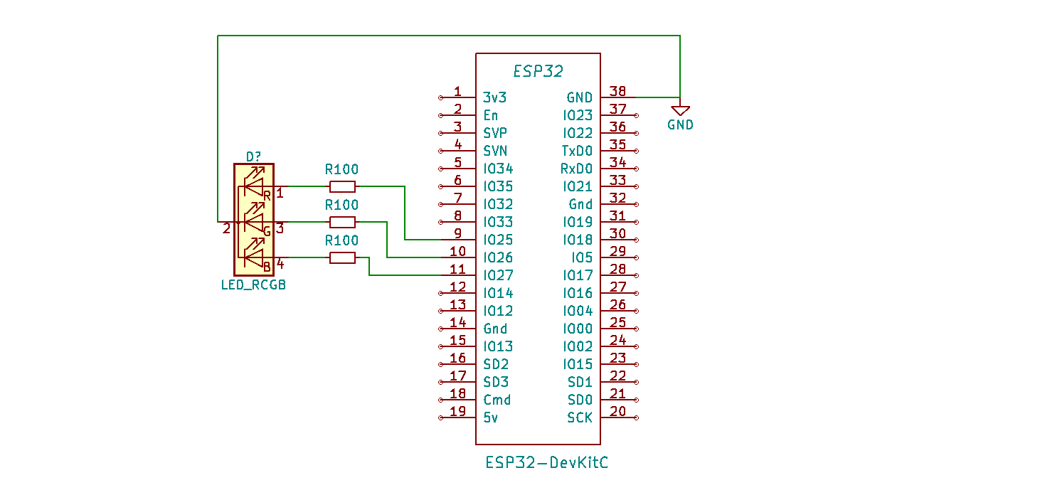
The RGB LED will be driven by GPIO 25, 26 and 27.
Application Code #
The following code snippets are excerpts. The whole source code is available in the src folder of this repository.
WIFI setup #
To connect the device to your local WIFI network, you need to configure its credentials information.
To do so, update the app_main() function, in the file src/main/main.c:
 wifi_config_t sta_config = {
   .sta = {
     .ssid = "your_access_point_name",
       .password = "your_ap_password",
       .bssid_set = false
   }
 };
Initialize Kuzzle #
Once connected to the WIFI netwok, initialize the Kuzzle library:
void on_light_state_update(cJSON* state); // State change from Kuzzle callback
static kuzzle_settings_t _k_settings = {
                    .host  = "kuzzle_host_ip_or_addr",
                    .port  = 1883,
                    .device_type  = "my-rgb-light",  // device identifier
                    .username = KUZZLE_IOT_DEVICE_USERNAME,
                    .password = KUZZLE_IOT_DEVICE_PASSWORD,
                    .on_fw_update_notification = NULL,
                    .on_device_state_changed_notification = on_light_state_update
};

esp_err_t event_handler(void* ctx, system_event_t* event)
{
    switch (event->event_id) {
        case SYSTEM_EVENT_STA_GOT_IP: {
            ESP_LOGI(TAG, "<<<<<<< GOT IP ADDR >>>>>>>>>");
            memcpy(_k_settings.device_id, uid, sizeof(k_device_id_t));
            kuzzle_init(&_k_settings);
        } break;
        case SYSTEM_EVENT_STA_DISCONNECTED: {
            ESP_LOGW(TAG, "Disonnected from AP...reconnecting...");
            esp_wifi_connect();
        } break;
        default:
            ESP_LOGW(TAG, ">>>>>>> event_handler: %d\n", event->event_id);
    }
    return ESP_OK;
}
LED Driver Code #
Initialize the LED driver:
// -- Hardware definition --
#define LEDC_MAX_PWM 8190
#define LEDC_TRANSITION_TIME 250 // ms
#define RED_PWM_CHANNEL LEDC_CHANNEL_0
#define RED_GPIO_NUM GPIO_NUM_25
#define GREEN_PWM_CHANNEL LEDC_CHANNEL_1
#define GREEN_GPIO_NUM GPIO_NUM_26
#define BLUE_PWM_CHANNEL LEDC_CHANNEL_2
#define BLUE_GPIO_NUM GPIO_NUM_27

static void _setup_light()
{
    static ledc_timer_config_t ledc_timer = {
        .bit_num    = LEDC_TIMER_13_BIT,    // set timer counter bit number
        .freq_hz    = 5000,                 // set frequency of pwm
        .speed_mode = LEDC_HIGH_SPEED_MODE, // timer mode,
        .timer_num  = LEDC_TIMER_0          // timer index
    };
    ledc_timer_config(&ledc_timer);

    static ledc_channel_config_t red = {
        .gpio_num   = RED_GPIO_NUM,
        .channel    = RED_PWM_CHANNEL,
        .speed_mode = LEDC_HIGH_SPEED_MODE,
        .intr_type  = LEDC_INTR_DISABLE,
        .timer_sel  = LEDC_TIMER_0,
        .duty       = 0 // LEDC channel duty, the duty range is [0, (2**bit_num) - 1],
    };

    static ledc_channel_config_t green = {
        .gpio_num   = GREEN_GPIO_NUM,
        .channel    = GREEN_PWM_CHANNEL,
        .speed_mode = LEDC_HIGH_SPEED_MODE,
        .intr_type  = LEDC_INTR_DISABLE,
        .timer_sel  = LEDC_TIMER_0,
        .duty       = 0 // LEDC channel duty, the duty range is [0, (2**bit_num) - 1],
    };

    static ledc_channel_config_t blue = {
        .gpio_num   = BLUE_GPIO_NUM,
        .channel    = BLUE_PWM_CHANNEL,
        .speed_mode = LEDC_HIGH_SPEED_MODE,
        .intr_type  = LEDC_INTR_DISABLE,
        .timer_sel  = LEDC_TIMER_0,
        .duty       = 0 // LEDC channel duty, the duty range is [0, (2**bit_num) - 1],
    };

    ledc_channel_config(&red);
    ledc_channel_config(&green);
    ledc_channel_config(&blue);
    ledc_fade_func_install(0);
}
The device keeps track of its current state (ON/OFF, RGB color...):
typedef struct light_state {
    uint8_t r;
    uint8_t g;
    uint8_t b;
    bool on; /// true if light is on
} light_state_t;

static light_state_t _light_state = {.r = 0xFF, .g = 0xFF, .b = 0xFF, .on = true};
Applying new state from Kuzzle to hardware #
When the state of the RGB light is changed in Kuzzle, our state callback is called.
It then updates the LED driver accordingly:
void on_light_state_update(cJSON* jresponse)
{
    cJSON* jstatus = cJSON_GetObjectItem(jresponse, "status");
    assert(jstatus != NULL);
    int16_t status_value = jstatus->valueint;
    ESP_LOGD(TAG, "Kuzzle response: status = %d", status_value);

    if (status_value == K_STATUS_NO_ERROR) {
        cJSON* jresult = cJSON_GetObjectItem(jresponse, "result");
        cJSON* jsource = cJSON_GetObjectItem(jresult, "_source");
        cJSON* jstate  = cJSON_GetObjectItem(jsource, "state");

        cJSON* r = cJSON_GetObjectItem(jstate, "r");
        if (r != NULL)
            _light_state.r = r->valueint;

        cJSON* g = cJSON_GetObjectItem(jstate, "g");
        if (g != NULL)
            _light_state.g = g->valueint;

        cJSON* b = cJSON_GetObjectItem(jstate, "b");
        if (b != NULL)
            _light_state.b = b->valueint;

        cJSON* on = cJSON_GetObjectItem(jstate, "on");
        if (on != NULL)
            _light_state.on = on->valueint;

        ESP_LOGD(TAG,
                 "New light state: r= 0x%02x, g= 0x%02x, b= 0x%02x, on = %s",
                 _light_state.r,
                 _light_state.g,
                 _light_state.b,
                 _light_state.on ? "true" : "false");
        _update_light();
    }
}

static void _update_light()
{
    uint32_t r_duty = _light_state.on ? (LEDC_MAX_PWM * _light_state.r) / 0xFF : 0;
    uint32_t g_duty = _light_state.on ? (LEDC_MAX_PWM * _light_state.g) / 0xFF : 0;
    uint32_t b_duty = _light_state.on ? (LEDC_MAX_PWM * _light_state.b) / 0xFF : 0;

    ledc_set_fade_with_time(LEDC_HIGH_SPEED_MODE, RED_PWM_CHANNEL, r_duty, LEDC_TRANSITION_TIME);
    ledc_set_fade_with_time(LEDC_HIGH_SPEED_MODE, GREEN_PWM_CHANNEL, g_duty, LEDC_TRANSITION_TIME);
    ledc_set_fade_with_time(LEDC_HIGH_SPEED_MODE, BLUE_PWM_CHANNEL, b_duty, LEDC_TRANSITION_TIME);

    ledc_fade_start(LEDC_HIGH_SPEED_MODE, RED_PWM_CHANNEL, LEDC_FADE_NO_WAIT);
    ledc_fade_start(LEDC_HIGH_SPEED_MODE, GREEN_PWM_CHANNEL, LEDC_FADE_NO_WAIT);
    ledc_fade_start(LEDC_HIGH_SPEED_MODE, BLUE_PWM_CHANNEL, LEDC_FADE_NO_WAIT);

    _publish_light_state(); // Publish new complete state
}
Get the Code #
The whole source code for the rgb light is available in the src folder.
Visualize the device state #
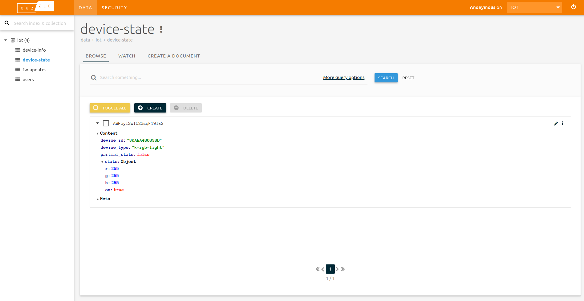
When booting, the device publishes its current state to Kuzzle. It can then be viewed in the administration console, as shown in the screenshot above:
- Open Kuzzle's Admin Console and connect it to your Kuzzle instance
- Open the
iotindex, and thedevice-statecollection in it - There should be a document representing the state of your RBG light
- Note the
device_idvalue down, as it will be used in the next step (it is built using the device MAC address)
Control the device state #
The device has subscribed to new documents written in the device-state collection: whenever a new document is created, Kuzzle notifies the device about it, in real-time.
We'll propose a partial state change to our device, to modify its color. The device then decides whether it accepts the new value, or not. If the change is accepted, the device sends its updated complete state to Kuzzle.
Click on the Create button and enter the following JSON:
{
  "device_id": "<the device_id retrieved from the previous step>",
  "partial_state": true,
  "state": {
    "r": 0
  }
}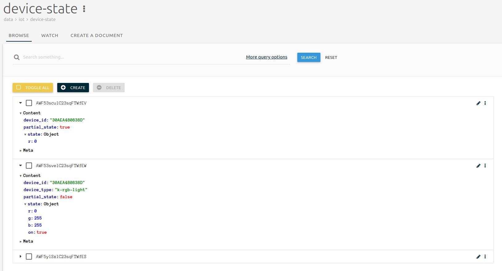
Once you click on the Create button to validate your document, the RGB light should turn to bright blue. When you refresh your browser, you should now have 3 documents:
- The initial one with r,g and b all set to 255,
- The partial one you entered, turning r to 0
- The new complete state published by the device with r set to 0 and g and b still set to 255

Going Further #
Check out the Kuzzle JS SDK to control your RGB light using a Javascript application: